Monday, 21 January 2013

BA5 Studio Project | Production #16


Asset #6 - Victorian Style Desk Chair


The next asset for my study environment scene I am going to work on is the desk chair which will be placed in front of the desk strangely ;) The designs I am looking at currently look intricate and I am fearful that I might not be able to maintain low poly modeling for the chair. I will have a go anyway and post up the results and go from there. 


Okay so I have now built the chair, well, I have built an incredibly basic version of this chair which isn’t identical but will do :P I did have a few problems to overcome and my original fears of it being too high poly are indeed true, I feel this chair would be, as Lothar says, “expensive” to run in game. I will have t show him, the good news is I would only have to figure out how to create a “dumbed down” version, as opposed to adding more detail. 


The key design areas I took from the reference image were: 


The cushioned top area of the chair for back support. 


The cushion on the actual seat part. 


The angle at which the legs come out of the chair. 


The short, high arm rests. 


The spokes at the back of the chair.


Trying to Fix the Strange Shadow :/


In order to create the pattern at the back of the chair I needed to create “holes “ in my mesh. My first idea was to use the INSERT EDGE LOOP tool to “cut” the back of the chair up so that I could DELETE FACES and then APPEND TO POLYGON the holes that I had left.


However, as you can see, every time I deleted a face and filled up the holes using the append to polygon tool I was left with this strange shadow on the top section of the chair. After numerous forum searches and a few panic attacks fearing I had duplicated faces and incorrect edges I decided this definitely wasn’t the “proper” way to build the shape I wanted. 


Attempt #2 - Using Extrude and Merge Vertices
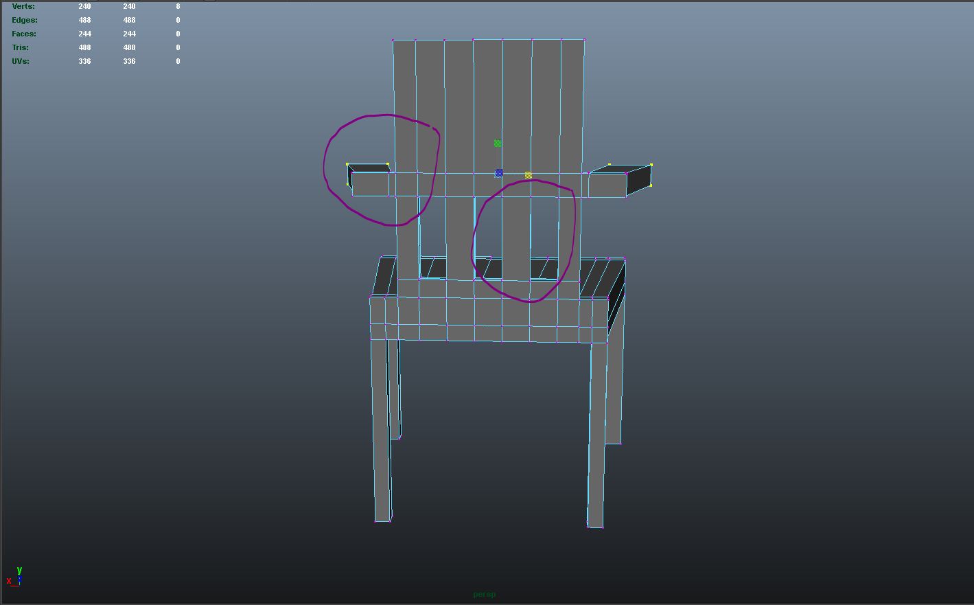
  
This was my next port of call, and I am ashamed that I didn’t try to do this first but hey, better late than never right? :P I SELECTED THE FACE I WANTED TO DELETE on both sides of the chair. I then SELECTED EXTRUDE and hit the “R” KEY to bring up the SCALE TOOL. From here I was able to PUSH THE SELECTED FACES INWARD TOWARDS EACH OTHE. When they were really close together I DELETED THE FACES and then RIGHT CLICKED VERTICIES which meant I was able to go to EDIT MESH > MERGE VERTICIES and merge the two sides together so that I was left with a gap but also the edges were filled. HOORAY, SUCCESS :D 


Creating the (not so) Intricate Chair “Bars”


As you can see in my reference image the chair has intricately detailed bars at the back which form a part of the back support. I knew from the start I couldn’t do anything overly fancy due to poly limitations and general Maya knowledge but by adding MULITPLE EDGE LOOPS around each of the middle bars, I was able to use the  MANIPULATION TOOLS to pull, pinch and resize the bards to add detail to them which helps them stay true to the reference image. 


Creating Definition Between the Chair and Cushion


In order for the cushion to be built upon I first had to use a BEVEL to differentiate between the cushion ad the wooden area of the chair.


Making The Padded Cushions


In order to get the plum volume in the cushions, to make that padded effect, I needed to play around with the  EDGES and VERTECIES. I would SELECT THEM and then PULL THEM UP to create the bump effect needed for the cushion. I would then DESLECT THE OUTER EDGES and CONTINUE TO RAISE THEM until I was left with the centre edges which I would pull the highest. This created a smooth rise which appeared like a cushion.


The Final Outcome

I am really happy with the way this chair turned out. Of course you don't have to be blind to see it isnt exactly the same in anway way but that image I posted was only a reference. Plus this excercise is fo rme to gain knowledge of Maya and problem solving which I did. I feel more confident everyday I deal with this programme. I know I am only at the basics but confidence is where it starts right? :P I still need to show my tutor this model as I fear it might be just too higher poly count to be considered effective for game engine. Even if I do have to produce a new model I wont be frustrated! :) 

Sunday, 20 January 2013

BA5 Studio Project | Production #15


Asset #05 - Wooden Museum Crate

Most environments in games have generic boxes of some description. For my museum study, to enhance the atmosphere (which is supposed to be unwelcoming) I want to include wooden crates (possibly delivery crates or crates containing un opened exhibitions). I don’t want to create a standard square crate, I want the shape to be slightly more interesting. Something like one of these.


 Simple geometry I know but I am proud of this box. It’s a little different to plain regular crates so I think it will work well within my level.

BA5 Studio Project | Production #14


Asset #04 - Victorian Style Floor Lamp

The structure of a floor lamp is pretty basic, from my research I can see that games don’t often model what the player cant see underneath the lamp shade itself; there isn’t a bulb or anything physically connecting the lampshade to the stand.  I want to create a floor lamp with an organic shape but also retain a low poly count. Here are some visual references for the  type of  floor lamp I would like to create. 


I struggled to get the shape of the lamp shade organic for this model but I am happy with the way it has turned out. Using vertices and edge loops (both on the outside of the model and inside) I was able to drag parts of the lamp shade in and out to create the desired curved effect similarly seen on the visual reference images I posted up. Whilst I could have taken it further by smoothing the mesh I feared the poly count was already too high as it was plus the mesh was becoming a tad messy which I really didn’t like so I have left it as it is for now. Another thing to note is how I have followed suit with the lamp shade design and left the  middle hollow because players just wouldn’t be looking there. I need to confirm this with Lothar before I leave it as finished though.

Friday, 18 January 2013

BA5 Studio Project | Production #13

Texture Tutorial with Lothar

Ambient Occlusion Maps


Yesterday our tutor Lothar gave us an incredibly helpful tutorial on UV mapping for textures with the main focus being around AMBIENT OCCLUSION MAPS which are used as a bas canvas upon which other textures can be applied. AMBIENT OCCLUSION MAPS mimic areas of shadow, for example if you had a tyre underneath a mud guard on a vehicle then you would want to bake on an AMBIENT OCCLUSION MAP in order for the wheel to appear as though there is a shadow being cast from the mud guard. All other textures applied over this in Photoshop will then have darker areas and you will know where shadows need to be placed instead of randomly painting them on without a clue.  


I tried to keep up and write as detailed set of notes and workflow as possible so I hope these make sense. I don’t have the time right now to create and bake my own occlusion map but I will do when I get round to texturing my museum study level.

.


Baked occlusion map: Black and white to create a shadow upon an object. Adds very fine detail. 


Shading: Hypershade > (Mental Ray) > surface shader > select mesh > right click (either on object or hyper shade surface shader square) > assign material to selection. 


Mental ray (Hypershade) > ambient occlusion (mb.amb.oclusion) > move it next to your surface shader in the Hypershade window > middle mouse drag white occlusion onto surface shader (in the Hypershade window) > default > double click ambient occlusion > (sample controls quality of “noise/texture” the ambient occlusion gives) possibly make it a bit darker. 


Back in perspective view > select rendering from top left dropdown on shelf > lighting and shading > batch bake (mental ray) > select square for options > “objects to bake” select the meshes you want to bake on > use bake set override > colour mode to occlusion > occlusion rays change the quality, the higher the number the higher the quality > X & Y resolution 1024 (double the size of the texture you want to use and dictates the size you want to use in photoshop) > convert and bake.

Using the Ambient Occlusion Map in Photoshop for New Textures


To get a snapshot of your UV go to UV editor > polygons> UV snapshot > change the resolution to what you set the ambient occlusion map to bake to (i.e. 1024) > you can use JPEG for this > you should be left with the UV lines from the texture editor.


Find the textures you want to use and ensure they are the same resolution as your ambient occlusion map > open ambient occlusion map and textures in photoshop.


Drag the UV lines (in photoshop) onto the ambient occlusion so that you get 2 layers in photoshop > ensure that the UV lines place perfectly over the ambient occlusion map > unlock the bottom layer and re name.


Create new layer > name it base > re colour it a neutral grey colour (avoid strong saturated colours like black and white) > ensure it is at the bottom of all the other layers > drag your texture onto your main file (this will become the 4th layer) > put it above the grey layer > rename > select ambient occlusion map > use the drop down menu under the layers and select multiply.


Now you can mess around with the settings on the texture layer (lighten, darken, saturate etc etc) > don’t edit the UV layers and do not flatten the image! 


Now you save it > save as > save as a Tiff > name it appropriately.


Hypershade editor > Blinn (used to simulate general surface textures such as wood, metal, glass; you can edit the transparency) > middle click drag the Blinn onto the mesh you want to work on > double click Blinn shader > under colour select options > file > find the ambient occlusion texture image you just created in Photoshop. 


If you want to make certain parts of your mesh a different texture to other parts (for example, the rubber ring around the tyre needs to be a rubber texture and the wheel needs to be a metal) you can select the different parts on the UV lines layer in Photoshop > grab the texture you want the selected parts to be > place the texture underneath the UV lines.


You can create new layers > select a colour > paint over the edges so that the different parts of the mesh blend (between the tyre and the metal). 
  
Specular Map Time (shine & matt)


Back on Photoshop (with the ambient occlusion map open) > create new group under layers > call it diffuse > select all layers bar UV lines and put them under the group.


New group > call it specular > re-save this as a jpeg > make it black and white > increase the contrast (optional) > once you have painted over the new jpeg you can drag it under specular on the TIFF file. (The more white you draw the shinier the object becomes).


Back to Maya > once you have double clicked specular map on the Hypershade window > under specular > colour > select the options to enable you to choose a file > choose the TIFF file with the new specular paint over.


TIP: For different types of map (such as reflective and specular) you start in Photoshop, paint on the effect over the UV map then apply it through Maya.

 I will be going into more detail with screen shots and examples of my own work but I am not at this stage yet in my work, I also need to pick the asset that I am going to texture, un wrap the UV's, organise them, find textures, THEN sort out the UV maps. Im scared and excited all at the same time :P