Progression With Fog
in UDK!! :D
Since my last post on FOG VOLUMES I have made major progress with UDK.
Whilst researching the various techniques to create fog in UDK I found this tutorial by Christopher Albeluhn who has a tutorial which demonstrates
how to manually build animated floor mist in
UDK. The only problem I faced was my lack
of knowledge working in UDK, especially with SHADERS/NODES/EXPRESSIONS, so I was put off giving this tutorial a
go because I thought it was a little to complex for me.
However, my friend Jack, whose work can be found HERE, had previously been working with the
shader/node network in UDK in order to create high quality moving water within
the engine. The water he built looked fantastic!
He took a look at the tutorial I was
scared of and stated it looked very similar to the water network he had been
working on. He then said he would take a closer look at it which was incredibly
lovely of him. He was then able to give me a better understanding of the
tutorial as we worked through together re creating the floor mist in UDK. Here
is my attempt at re creating the floor mist in UDK! :D
Following
Christopher Albeluhn’s UDK Fog Tutorial
As Albeluhn states, the shader created
consists of a single, and ultimately flat 2D, texture which has various nodes
attached to it such as “bump offset” in order for the texture to animate and
appear as fog.


I began by creating a 1024 x 1024
canvas on Photoshop, I then used the cloud filter that is built in to create a
randomised cloud texture. For the tutorial I needed 3 random and different
cloud textures so I went ahead and created 2 more. I named them RED BLUE and GREEN.

I had to change 2 of the 3 cloud
textures to greyscale but keep 1 in RGB. I did this by selecting the texture
and changing the colour mode on Photoshop. I then selected the channels of the
RGB colour mode version and copy and pasted the other two greyscale cloud
textures under their corresponding channels.


Here you can see examples of the
original cloud textures and the colour version demonstrates how the texture
looked once I had copied the greyscale versions of the cloud under the correct
channel attributes on Photoshop. The texture was then ready to put into UDK.
“[…] a combination of 3 different cloud
textures. Each cloud texture takes up a different RGB channel, this will allow
you to have 3 different texture options in a single texture.”

I then switched into UDK and created a
new package for my project. Packages in UDK contain all the different “set
pieces” that make up your level. This includes materials, models, noises and
player triggers etc. Basically anything you have used to build your level is all in one convenient
place.

I then switched programmes again, this
time over to Maya, where I created a basic poly plane which matched the
dimensions of my Photoshop texture (in this case, 1024)).


I then exported my poly plane as an FBX
into UDK and saved it into my new UDK package that I created specially for this
project.

As you can see the imported poly plane
from Maya shows up (FogPlaneBob) in the
content browser under the fog package I created. I then imported the RGB cloud
texture from Photoshop into the same package.

I then simply right clicked in the
content browser and selected “new material” which bought up this screen. This
is the screen I need to build the new fog material from the texture.

To begin the node network I needed to
choose a “texture coordinate”. I am
going to do research into the various nodes I can use soon but for now Jack
walked me through giving me an overall understanding of the nodes where he
could. Texture nodes are used so that we can use various textures and place
them separately. The texture node literally tells the material what part of the
texture to look at and where to focus. At the bottom you can enter different
coordinate values which depict the specific location to look at.

After I created four TextureCoordinates I needed to create four Panners. Panner is used to create movement in
textures.

This shot shows how I connected the TextureCoordinates to the Panner materials.

This screen illustrates how I then
inserted my textures (that I made in Photoshop) and linked to the Panner and TextureCoordinates. The
texture is named TextureSample.

I then inserted two more TextureCoordinates and two Add material expressions. I hooked the top
two TextureSamples to the Add, one from the green to the value A and the other from the blue to the B value output. Add expressions
takes two inputs and adds them together. It adds them together by reading the
information in the channels of the texture. R, G and B values get added into
the expression.
Then I added another two Panner expressions and linked the TextureCoordinates to them.

I then insert two BumpOffset expressions and link the two Add’s into the height option and the two Panners into the coordinate section. BumpOffset allows a texture to appear as if it has
depth, it’s a work of illusion, without the need for additional geometry.

I then inserted two more of my textures
which I linked to the BumpOffset.

The tutorial then instructed me to
insert another Add expression
and link the final two TextureSamples to it as
seen above.

I then added two new expressions, a ConstantVector and an Power expression. I linked the Add expression to the base of the Power and I linked the ConstantVector to the Exp of the Power.

Here you can see another new expression
added which is called a ConstantClamp. Its job
is to stop components exceeding specific minimum and maximum values.

And there it is, the entire diffuse
node network of expression materials that create the first part of the fog
material
:D

Then it was time to begin the Opacity network for the fog material. I began
by inserting a DepthBiasedAlpha. This
expression essentially removes and sharp edges that might occur when the
multiple textures intersect.

I then added two Multiply expressions.
I linked the DepthBiasedAlpha from its Alpha selection to the first Multiply and then added the other Bias selection into the other Multiply.

This is where the diffuse network interacts with the opacity network. I inserted another ConstantVector and attached the B selection from the Multiply to it. I then linked the A selection into the Add from the diffuse network as seen above.
That completes the Opacity network, I just had to link it onto the
opacity selection on the left to finish it.

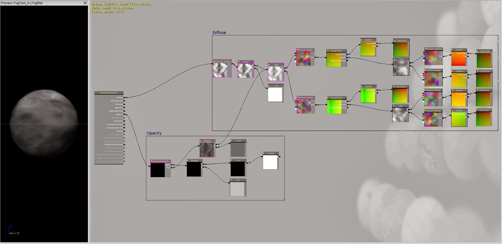
Here is a screen capture showing my
completed node network of material expressions, split between diffuse and
opacity to create the fog material seen in the fog package that I created in
UDK previously.

This is a very basic and simple
environment I created with a static floor, wall and ceiling mesh from the
content browser in UDK. Once I had created it I dragged my poly plane created
in Maya onto the scene and then simply dragged my newly created fog material
onto it. I then used the wireframe mode in UDK to see the edges of the fog
material in order to place it just above the floor so that it appeared as floor
fog.

This is how the fog appeared before I
rebuilt the lighting. You can see the edges quite clearly but this was only a
test and practice run through.

And here is the final result. Obviously
you cant
see the animated fog but I promise you, it moves ;) I plan to re create the fog
on my own now that Jack has given me a good head start in understanding the
node network and material expressions. I also plan to create a scene with the
fog in that is slightly more advance than just a basic room like this but I am
really happy that I have made this, it gives me confidence for the next time I
build the fog :D
No comments:
Post a Comment